222 Transmitter/beacon project
Updated: October 29th
Well, this looks promising! I spent about 2 hours today over at Doug's (VE3XK) house and we took a good look at this transmitter.
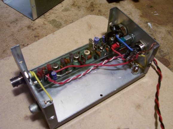
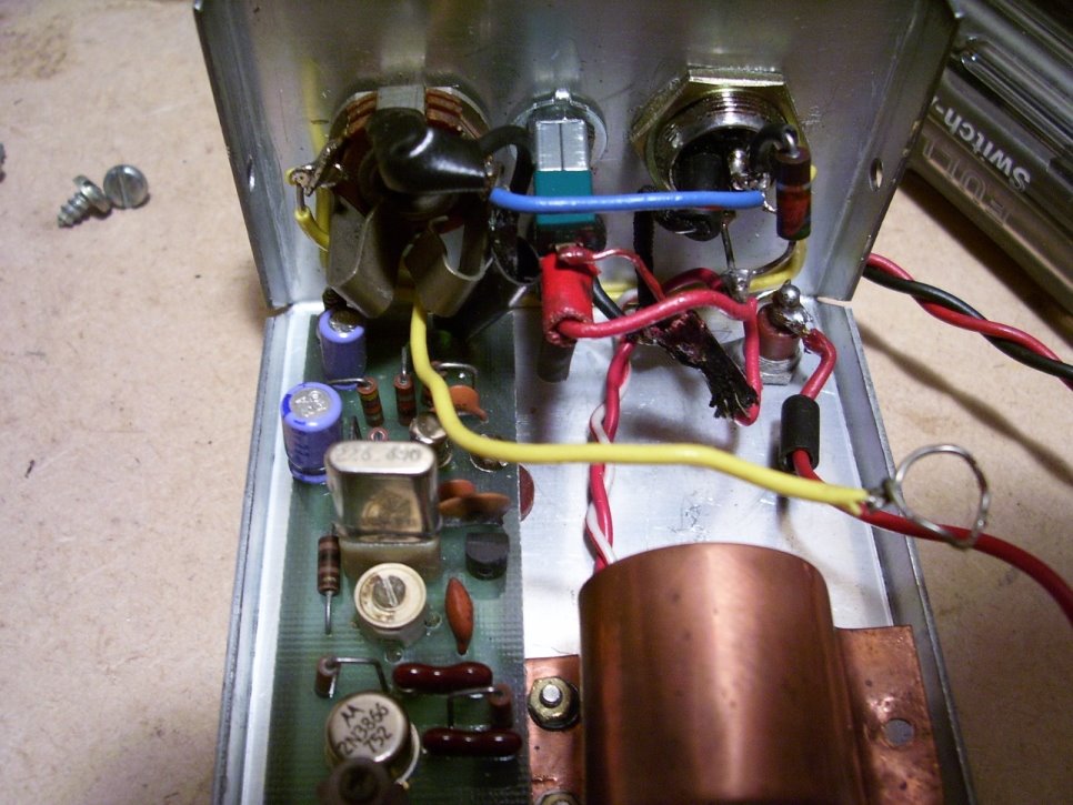
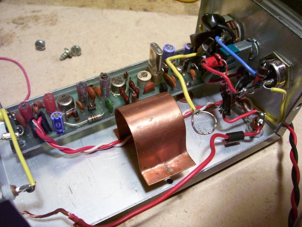
We walked though the design and how it is wired in the case using the schematic for the newer design (TX-220B) as a general guide. It appears the previous owner of this kit used a microphone (standard 4-connector) as well as a stereo plug for audio input. The stereo plug is a non-standard size (about 1/5 ") which may be a telephony plug. The RCA jack on the case was setup, we believe, as input to a frequency counter as the lead from the RCA jack was coiled (see yellow wire in picture) around the RF output lead in order to "sense" RF. Pretty smart!
We believe that the previous owner had a 12V battery installed inside the case (held in place by the copper clamp) that was wired to provide power in case the external power was down. We removed this clamp and leads to tidy up the case a bit.

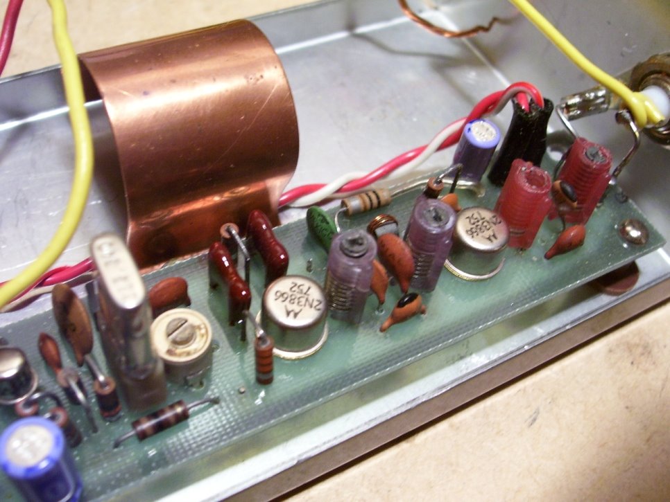
We then noticed the writing on the label outside the case (probably should have read this first ;-) which stated that there was a missing capacitor on the output stage. On reviewing the board we found where this capacitor should go. In reviewing the design for the 220B we deduced that this capacitor is part of the PA circuit and would work with the coil to set the frequency.
At this point we decided to appy 12v to see what happens. Our best guess was that we would get some RF out at a frequency not to far from the crystal frequency.
We connected the transmitter to a dummy load and applied power. According to my Radio-Shack Frequency Counter (Model 22-306) we were seeing some weak RF at about 350 MHz. This is much higher than 223 MHz but this seemed reasonable considering the missing capacitor in the final stage. Success!
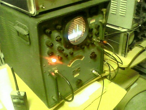
To try to impress me (and it worked ;-) Doug fired up his 1940's vintage Oscilloscope (pics below) and we took at a look at the output from the transmitter. It showed a nice signal at about 350 MHz. We then "keyed" the tranmitter via the power lead to see if the transmitter would respond quickly.. and it did! More good news!


Now that we basically know that this kit is complete (minus the missing capacitor) my next step is to wait until the manual arrives (ordered from Ham Radio Manuals) to determine what size capacitor to add. Then I will pull the board out of the case, add the capacitor and see if we are in good shape. The current crystal is set at 223.340 which in the FM portion of the 222 band. As this will eventually be a CW beacon I will need to order a crystal in the appropriate frequency (somewhere around 222.050).
Other changes I need to make include adding PowerPole connectors and a fuse to the power leads and also removing the microphone jack as it will not be needed.
Next I will need to determine how to key this tranmistter to act as a beacon. One option is to key via 12v which will requrie a voltage regulator as well as the beacon keyer. We will see! I have ordered a smart-keyer kit that, once built, will be used to provide the morse code to this beacon transmitter.
Thanks to VE3XK, VE3CVG, VE3BYT and VA3CDD for all the help and moral assistance !
***********************************8
First Post:
Here are some pics of my latest Ebay purchase. It is a VHF Engineering 222 transmitter (TX-220) thatI am hoping to press into service as a 222 beacon.
Some info on the VHF Engineering kits including the TX-220B (not quite the same as this one) are located HERE.


Hopefully this will eventuallly be part of a series of VHF/UHF beacons put on the air by the WCARC.
Well, this looks promising! I spent about 2 hours today over at Doug's (VE3XK) house and we took a good look at this transmitter.
We walked though the design and how it is wired in the case using the schematic for the newer design (TX-220B) as a general guide. It appears the previous owner of this kit used a microphone (standard 4-connector) as well as a stereo plug for audio input. The stereo plug is a non-standard size (about 1/5 ") which may be a telephony plug. The RCA jack on the case was setup, we believe, as input to a frequency counter as the lead from the RCA jack was coiled (see yellow wire in picture) around the RF output lead in order to "sense" RF. Pretty smart!
We believe that the previous owner had a 12V battery installed inside the case (held in place by the copper clamp) that was wired to provide power in case the external power was down. We removed this clamp and leads to tidy up the case a bit.
We then noticed the writing on the label outside the case (probably should have read this first ;-) which stated that there was a missing capacitor on the output stage. On reviewing the board we found where this capacitor should go. In reviewing the design for the 220B we deduced that this capacitor is part of the PA circuit and would work with the coil to set the frequency.
At this point we decided to appy 12v to see what happens. Our best guess was that we would get some RF out at a frequency not to far from the crystal frequency.
We connected the transmitter to a dummy load and applied power. According to my Radio-Shack Frequency Counter (Model 22-306) we were seeing some weak RF at about 350 MHz. This is much higher than 223 MHz but this seemed reasonable considering the missing capacitor in the final stage. Success!
To try to impress me (and it worked ;-) Doug fired up his 1940's vintage Oscilloscope (pics below) and we took at a look at the output from the transmitter. It showed a nice signal at about 350 MHz. We then "keyed" the tranmitter via the power lead to see if the transmitter would respond quickly.. and it did! More good news!

Now that we basically know that this kit is complete (minus the missing capacitor) my next step is to wait until the manual arrives (ordered from Ham Radio Manuals) to determine what size capacitor to add. Then I will pull the board out of the case, add the capacitor and see if we are in good shape. The current crystal is set at 223.340 which in the FM portion of the 222 band. As this will eventually be a CW beacon I will need to order a crystal in the appropriate frequency (somewhere around 222.050).
Other changes I need to make include adding PowerPole connectors and a fuse to the power leads and also removing the microphone jack as it will not be needed.
Next I will need to determine how to key this tranmistter to act as a beacon. One option is to key via 12v which will requrie a voltage regulator as well as the beacon keyer. We will see! I have ordered a smart-keyer kit that, once built, will be used to provide the morse code to this beacon transmitter.
Thanks to VE3XK, VE3CVG, VE3BYT and VA3CDD for all the help and moral assistance !
***********************************8
First Post:
Here are some pics of my latest Ebay purchase. It is a VHF Engineering 222 transmitter (TX-220) thatI am hoping to press into service as a 222 beacon.
Some info on the VHF Engineering kits including the TX-220B (not quite the same as this one) are located HERE.
Hopefully this will eventuallly be part of a series of VHF/UHF beacons put on the air by the WCARC.
posted by Zinck Family at 4:45 PM
0 comments
![]()
